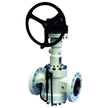
General Plug Valve (Double block & bleed valve)

Introduction
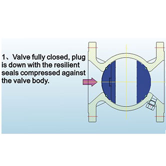
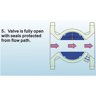
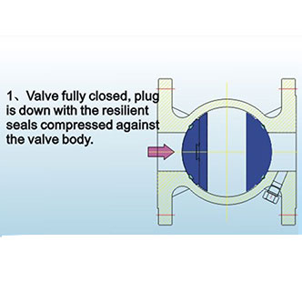
Double block & bleed valve (DBBV) is a non-lubricated, resilient seal, plug-type valve which has a mechanical means of freeing the plug before it is rotated from the closed to the open position.
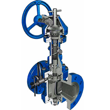
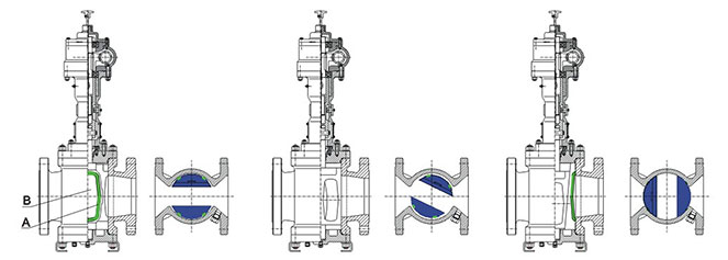
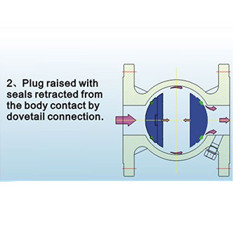
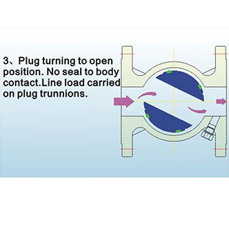
In opening the valve, the plug is raised, thus retracting the seating segments or slips through their tapered dovetail connections. Only after the slips are fully retracted from the body seat is the plug rotated to the open position.
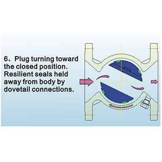
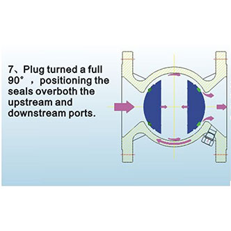
Conversely, in closing the valve, the plug and slips are rotated freely, with no seal-to-body contact until the slips are positioned over the ports.
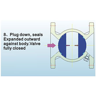
Then the plug is driven down between the slips and the tapered surfaces wedge out the slips for a positive upstream as well as downstream shut-off.
The small DBB general plug valve is handwheel operated, and require up to 3 turns to open or close. Up to 2 3/4 turns expand or retract the slips, while turn rotates the plug. Large valves operate in a similar manner, except that they have enclosed weather-proof worm gearing.
At the top of the valve, a position indicator flag shows the exact plug position. It appears in line with the flow when the valve is open and perpendicular to the flow when the valve is closed.
Since DBBV hold bubble-tight, for ease of opening in liquid service, it is important to prevent trapped body pressure from exceeding the working pressure of the valve.
Therefore, a relief system is required to prevent pressure buildup in the body cavity.
For maximum upstream sealing, do not back off the hand wheel.
Warning: Do not over torque by using cheater bars.
Pressure Test
| ASME Class | 150 | 300 | 600 | 900 | Result | |
| Shell Test Pressure (Valve Open) |
(Pisg) (kg/cm2) |
500 35 |
1200 85 |
2250 158 |
3350 235 |
No Leakage Permitted |
| Seat Test Pressure | (Pisg) | 300 | 800 | 1600 | 2400 | Test upstream & downstream |
| (Valve Closed) | (kg/cm2) | 21 | 56 | 113 | 168 | Seats. No leakage permitted |
| Supplementary (API 598) Air Seat Test Pressure |
(Pisg) | 80 | 80 | 80 | 80 | Test upstream & downstream |
| (Valve Closed) | (kg/cm2) | 6 | 6 | 6 | 6 | Seats. No leakage permitted |
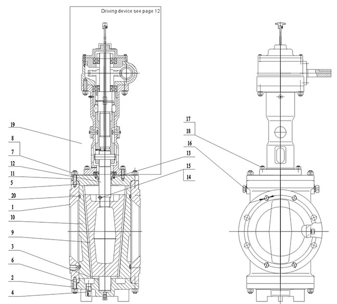
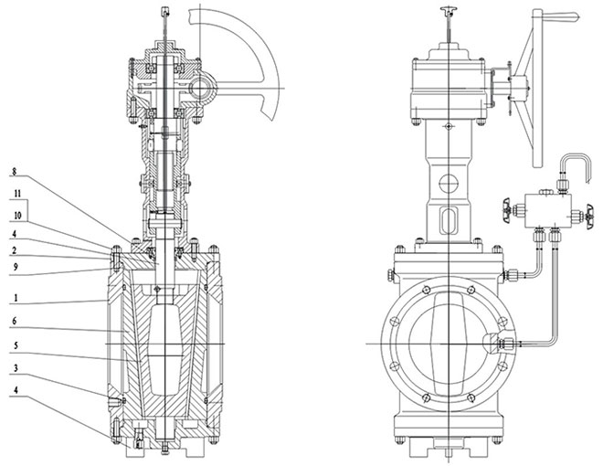
Structure of Short Pattern with Handle Wheel
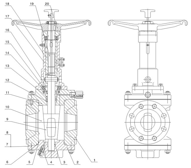
| 1 | 2 | 3 | 4 | 5 | 6 | 7 | 8 | 9 | 10 |
| Body | Cover | Bearing | Drain valve | O-ring | Spiral Wounded Gasket |
Stud | Nut | Plug | Disc |
| 11 | 12 | 13 | 14 | 15 | 16 | 17 | 18 | 19 | 20 |
| Upper Cover | Upper Bearing |
Seal ring | O-ring | Packing | Packing Gland |
Yoke | Slide Bushing |
Stem | Hand Wheel |
Structure of Short Pattern with Gear
| 1 | 2 | 3 | 4 | 5 | 6 | 7 | 8 | 9 | 10 |
| Body | Lower Cover | Non-lubricated bearing |
Drain Valve | O-ring | FS Gasket | Stud | Nut | Plug | Disc |
| 11 | 12 | 13 | 14 | 15 | 16 | 17 | 18 | 19 | 20 |
| Upper Cover | Stem | FS Packing | Pin | Inner Hex Screw |
Block | Stud | Nut | Driving device | Seal Ring |
Structure of Reduced Bore Type with Gear
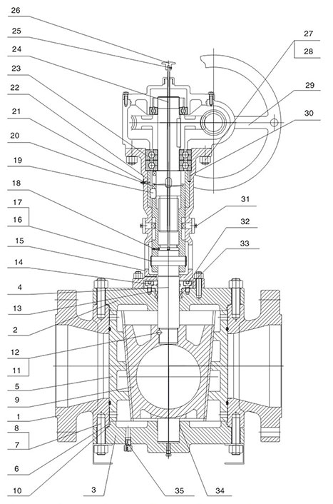
| 1 | 2 | 3 | 4 | 5 | 6 | 7 | 8 | 9 | 10 |
| Body | Lower Cover | Non-lubricated bearing |
Drain Valve | O-ring | FS Gasket | Stud | Nut | Plug | Disc |
| 11 | 12 | 13 | 14 | 15 | 16 | 17 | 18 | 19 | 20 |
| Upper Cover | Stem | FS Packing | Pin | Inner Hex Screw |
Packing Gland |
Block | Stud | Nut | Handwheel |
| 21 | 22 | 23 | 24 | 25 | 26 | 27 | 28 | 29 | 30 |
| Seal Ring | Guiding Bush | Shaft Bushing | Indicating Arm | Set Screw | Pointer | Nut | Stud | Handwheel | Pin |
| 31 | 32 | 33 | 34 | 35 | |||||
| Seal Ring | Inner Hex Screw |
FS Packing | Bearing | Drain Valve |
Structure of Full Bore Type with Gear
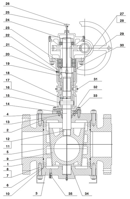
| 1 | 2 | 3 | 4 | 5 | 6 | 7 | 8 | 9 | 10 |
| Body | Lower Cover | Non-lubricated Bearing |
Drain Valve | O-ring | FS Gasket | Stud | Nut | Plug | Disc |
| 11 | 12 | 13 | 14 | 15 | 16 | 17 | 18 | 19 | 20 |
| Upper Cover | Stem | FS Packing | Pin | Inner Hex Screw |
Emgency seal device | Plug | Bolt | Nut | Driving Device |
| 21 | 22 | 23 | 24 | 25 | 26 | 27 | 28 | 29 | 30 |
| Seal Ring | Guiding Bush | Bearing | Indicating Arm |
Set Screw | Pointer | Nut | Bolt | Hand Wheel | Pin |
| 31 | 32 | 33 | 34 | 35 | |||||
| Inner Hex Screw |
Inner Hex Bolt |
FS Packing | Bearing | Drain Valve |
Structure of Gear
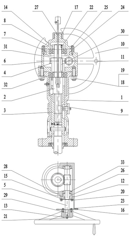
| NO. | Name |
| 1 | Yoke |
| 2 | Driving Stem |
| 3 | Driving Bushing |
| 4 | Worm Gear |
| 5 | Gear Stem |
| 6 | Box |
| 7 | Bearing Seat |
| 8 | Box Cover |
| 9 | Indicating Arm |
| 10 | HW |
| 11 | Lever |
| 12 | End cover |
| 13 | Gasket |
| 14 | Lockable Nut |
| 15 | Locking Nose |
| 16 | Lock Pad |
| 17 | Cover Cap |
| 18 | Nut |
| 19 | Stud |
| 20 | Bolt |
| 21 | Bolt |
| 22 | Lock screw |
| 23 | Bolt |
| 24 | Bolt |
| 25 | O-ring |
| 26 | O-ring |
| 27 | O-ring |
| 28 | O-ring |
| 29 | O-ring |
| 30 | Normal Key |
| 31 | Normal Key |
| 32 | Shaft Washer |
| 33 | Oil Cup |
| 34 | Bearing |
| 35 | Bearing |
Materials
| Number | Name | Material | ||
| 1 | Body | Casting steel ASTM A216 WCB, body inside Cr plated |
Casting steel ASTM A352 LCB, body inside Cr plated |
Casting steel ASTM A351 Cf8 |
| 2 | Upper cover | Forged steel ASTM A105 | Forged steel ASTM A105 | Forged steel ASTM A182 F304 |
| 3 | Lower corer | Casting steel ASTM A216 WCB | Casting steel ASTM A352 LCB | Casting steel ASTM A351 CF8 |
| 4 | Stem | ASTM A182 F6a | ASTM A182 F6a | ASTM A182 F6a |
| 5 | Plug | Casting steel ASTM A216 WCB, surface ENP |
Casting steel ASTM A352 LCB, surface ENP |
Casting steel ASTM A351 Cf8 |
| 6 | Disc | A536 65-45-12 | A536 65-45-12 | Casting steel ASTM A351 Cf8 |
| 7 | Seal ring | Viton | Viton | Viton |
| 8 | Packing | Expanded graphite | Expanded graphite | Expanded graphite |
| 9 | O-ring | Viton | Viton | Viton |
| 10 | Stud | ASTM A 193 B7 | ASTM A 193 B7 | ASTM A 193 B8 |
| 11 | Nut | ASTM A 194 2H | ASTM A 194 2H | ASTM A 194 8 |
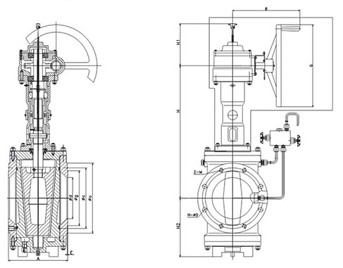
Dimension of Short Pattern with Handwheel

| Class | NPS | A | d | g | c | o | T | E | N-ΦD | H | H1 | G | Wt | Cv |
| 150 | 2 | 178 | 50 | 92 | 120.7 | 150 | 14.3 | 2 | 4-19 | 470 | 135 | 250 | 26 | 190 |
| 3 | 203 | 76 | 127 | 152.4 | 190 | 17.5 | 2 | 4-19 | 517 | 159 | 300 | 34 | 254 | |
| 4 | 229 | 100 | 157.2 | 190.5 | 230 | 22.3 | 2 | 8-19 | 573 | 185 | 400 | 72 | 582 | |
| 6 | 267 | 150 | 215.9 | 241.3 | 280 | 23.9 | 2 | 8-22.5 | 712 | 215 | 450 | 107 | 1360 | |
| 8 | 292 | 201 | 269.9 | 298.5 | 345 | 27 | 2 | 8-22.5 | 760 | 288 | 500 | 210 | 2250 | |
| 300 | 2 | 216 | 50 | 92 | 127 | 165 | 20.7 | 2 | 8-19 | 470 | 135 | 250 | 30 | 201 |
| 3 | 283 | 76 | 127 | 168.3 | 210 | 27 | 2 | 8-22.5 | 530 | 159 | 350 | 43 | 265 | |
| 4 | 305 | 100 | 157.2 | 200 | 255 | 30.2 | 2 | 8-22.5 | 577 | 185 | 450 | 86 | 610 | |
| 6 | 403 | 150 | 215.9 | 269.9 | 320 | 35 | 2 | 12-22.5 | 712 | 220 | 550 | 180 | 1680 | |
| 600 | 2 | 292 | 50 | 92 | 127 | 165 | 25.4 | 7 | 8-19 | 515 | 139 | 350 | 52 | 275 |
| 3 | 356 | 76 | 127 | 168.3 | 210 | 31.8 | 7 | 8-22.5 | 530 | 159 | 400 | 77 | 290 | |
| 4 | 432 | 100 | 157.2 | 215.9 | 275 | 38.1 | 7 | 8-25.5 | 618 | 190 | 500 | 120 | 830 |
| PN | DN | A | d | 9 | c | 0 | T | E | N-ΦD | H | H1 | G | Wt | Cv |
| 1.6 | 50 | 178 | 50 | 100 | 125 | 160 | 16 | 3 | 4-18 | 470 | 135 | 250 | 26 | 190 |
| 80 | 203 | 76 | 135 | 160 | 195 | 20 | 3 | 8-18 | 517 | 159 | 300 | 34 | 254 | |
| 100 | 229 | 100 | 155 | 180 | 215 | 20 | 3 | 8-18 | 573 | 185 | 400 | 72 | 582 | |
| 150 | 267 | 150 | 210 | 240 | 280 | 24 | 3 | 8-22 | 712 | 215 | 450 | 107 | 1360 | |
| 200 | 292 | 201 | 265 | 295 | 335 | 26 | 3 | 12-23 | 760 | 288 | 500 | 210 | 2250 | |
| 2.5 | 50 | 216 | 50 | 100 | 125 | 160 | 20 | 3 | 4-18 | 470 | 135 | 250 | 30 | 201 |
| 80 | 283 | 76 | 135 | 160 | 195 | 22 | 3 | 8-18 | 530 | 159 | 350 | 43 | 265 | |
| 100 | 305 | 100 | 160 | 190 | 230 | 24 | 3 | 8-23 | 577 | 185 | 450 | 86 | 610 | |
| 150 | 403 | 150 | 218 | 250 | 300 | 30 | 3 | 8-25 | 712 | 220 | 550 | 180 | 1680 | |
| 4.0 | 50 | 216 | 50 | 100 | 125 | 160 | 20 | 3 | 4-18 | 470 | 135 | 250 | 30 | 201 |
| 80 | 283 | 76 | 135 | 160 | 195 | 22 | 3 | 8-18 | 530 | 159 | 350 | 43 | 265 | |
| 100 | 305 | 100 | 156 | 190 | 230 | 24 | 3 | 8-23 | 577 | 185 | 450 | 86 | 610 | |
| 150 | 403 | 150 | 218 | 250 | 300 | 30 | 3 | 8-25 | 712 | 220 | 550 | 180 | 1680 | |
| 6.3 | 50 | 292 | 50 | 105 | 135 | 175 | 26 | 3 | 4-23 | 515 | 139 | 350 | 52 | 275 |
| 80 | 356 | 76 | 140 | 170 | 210 | 30 | 3 | 8-23 | 530 | 159 | 400 | 77 | 290 | |
| 100 | 432 | 100 | 168 | 200 | 250 | 32 | 3 | 8-25 | 618 | 190 | 500 | 120 | 830 | |
| 10 | 50 | 292 | 50 | 112 | 145 | 195 | 28 | 3 | 4-25 | 515 | 139 | 350 | 52 | 275 |
| 80 | 356 | 76 | 148 | 180 | 230 | 34 | 3 | 8-25 | 530 | 159 | 400 | 77 | 290 | |
| 100 | 432 | 100 | 172 | 210 | 265 | 38 | 4.5 | 8-30 | 618 | 190 | 500 | 120 | 830 |
Dimension of Short Pattern with Gear
| Class | NPS | A | d | g | c | o | T | E | N-ΦD | H | H1 | H2 | G | B | Wt | Cv |
| 150 | 2 | 178 | 50 | 92 | 120.7 | 150 | 14.3 | 2 | 4-19 | 412 | 155 | 135 | 320 | 265 | 35 | 190 |
| 3 | 203 | 76 | 127 | 152.4 | 190 | 17.5 | 2 | 4-19 | 429 | 155 | 159 | 320 | 265 | 48 | 254 | |
| 4 | 229 | 100 | 157.2 | 190.5 | 230 | 22.3 | 2 | 8-19 | 454 | 155 | 185 | 320 | 265 | 88 | 582 | |
| 6 | 267 | 150 | 215.9 | 241.3 | 280 | 23.9 | 2 | 8-22.5 | 575 | 185 | 215 | 460 | 330 | 126 | 1360 | |
| 8 | 292 | 201 | 269.9 | 298.5 | 345 | 27 | 2 | 8-22.5 | 656 | 185 | 288 | 460 | 330 | 246 | 2250 | |
| 10 | 330 | 252 | 323.8 | 362 | 405 | 28.6 | 2 | 12-25.5 | 734 | 185 | 333 | 460 | 330 | 289 | 3506 | |
| 12 | 356 | 303 | 381 | 431.8 | 485 | 30.2 | 2 | 12-25.5 | 752 | 194 | 350 | 460 | 372 | 458 | 3920 | |
| 14 | 381 | 334 | 412.8 | 476.3 | 535 | 33.4 | 2 | 12-28.5 | 808 | 194 | 385 | 460 | 372 | 560 | 5420 | |
| 16 | 406 | 385 | 469.9 | 539.8 | 595 | 35 | 2 | 16-28.5 | 847 | 210 | 417 | 500 | 400 | 775 | 6910 | |
| 300 | 2 | 216 | 50 | 92 | 127 | 165 | 20.7 | 2 | 8-19 | 412 | 155 | 135 | 320 | 265 | 42 | 201 |
| 3 | 283 | 76 | 127 | 168.3 | 210 | 27 | 2 | 8-22.5 | 429 | 155 | 159 | 320 | 265 | 55 | 265 | |
| 4 | 305 | 100 | 157.2 | 200 | 255 | 30.2 | 2 | 8-22.5 | 454 | 155 | 185 | 320 | 265 | 88 | 610 | |
| 6 | 403 | 150 | 215.9 | 269.9 | 320 | 35 | 2 | 12-22.5 | 575 | 185 | 215 | 460 | 330 | 185 | 1680 | |
| 8 | 419 | 201 | 269.9 | 330.2 | 380 | 39.7 | 2 | 12-25.5 | 656 | 185 | 288 | 460 | 330 | 362 | 2955 | |
| 10 | 457 | 252 | 323.8 | 387.4 | 445 | 46.1 | 2 | 16-28.5 | 734 | 185 | 333 | 460 | 330 | 462 | 3490 | |
| 12 | 502 | 303 | 381 | 450.8 | 520 | 49.3 | 2 | 16-32 | 752 | 194 | 350 | 460 | 372 | 736 | 4630 | |
| 600 | 2 | 292 | 50 | 92 | 127 | 165 | 25.4 | 7 | 8-19 | 430 | 180 | 140 | 320 | 280 | 54 | 275 |
| 3 | 356 | 76 | 127 | 168.3 | 210 | 31.8 | 7 | 8-22.5 | 445 | 180 | 159 | 320 | 280 | 80 | 290 | |
| 4 | 432 | 100 | 157.2 | 215.9 | 275 | 38.1 | 7 | 8-25.5 | 525 | 185 | 190 | 460 | 330 | 145 | 830 | |
| 6 | 559 | 150 | 215.9 | 292.1 | 355 | 47.7 | 7 | 12-28.5 | 655 | 194 | 249 | 460 | 372 | 360 | 2235 | |
| 8 | 660 | 201 | 269.9 | 349.2 | 420 | 55.6 | 7 | 12-32 | 760 | 210 | 310 | 500 | 400 | 574 | 3550 |
| PN | DN | A | d | g | c | o | T | E | N-ΦD | H | H1 | H2 | G | B | Wt | Cv |
| 1.6 | 50 | 178 | 50 | 100 | 125 | 160 | 16 | 3 | 4-18 | 412 | 155 | 135 | 320 | 265 | 35 | 190 |
| 80 | 203 | 76 | 135 | 160 | 195 | 20 | 3 | 8-18 | 429 | 155 | 159 | 320 | 265 | 48 | 254 | |
| 100 | 229 | 100 | 155 | 180 | 215 | 20 | 3 | 8-18 | 454 | 155 | 185 | 320 | 265 | 88 | 582 | |
| 150 | 267 | 150 | 210 | 240 | 280 | 24 | 3 | 8-23 | 575 | 185 | 215 | 460 | 330 | 126 | 1360 | |
| 200 | 292 | 201 | 265 | 295 | 335 | 26 | 3 | 12-23 | 656 | 185 | 288 | 460 | 330 | 246 | 2250 | |
| 250 | 252 | 323.8 | 320 | 355 | 405 | 30 | 3 | 12-25 | 734 | 185 | 333 | 460 | 330 | 289 | 3506 | |
| 300 | 303 | 381 | 375 | 410 | 460 | 30 | 3 | 12-25 | 752 | 194 | 350 | 460 | 372 | 458 | 3920 | |
| 350 | 381 | 334 | 435 | 470 | 520 | 34 | 3 | 16-25 | 808 | 194 | 385 | 460 | 372 | 560 | 5420 | |
| 400 | 406 | 385 | 485 | 525 | 580 | 36 | 3 | 16-30 | 847 | 210 | 417 | 500 | 400 | 775 | 6910 | |
| 2.5 | 50 | 216 | 50 | 100 | 125 | 160 | 20 | 3 | 4-18 | 412 | 155 | 135 | 320 | 265 | 42 | 201 |
| 80 | 283 | 76 | 135 | 160 | 195 | 22 | 3 | 8-18 | 429 | 155 | 159 | 320 | 265 | 55 | 265 | |
| 100 | 305 | 100 | 160 | 190 | 230 | 24 | 3 | 8-23 | 454 | 155 | 185 | 320 | 265 | 88 | 610 | |
| 150 | 403 | 150 | 218 | 250 | 300 | 30 | 3 | 8-25 | 575 | 185 | 215 | 460 | 330 | 185 | 1680 | |
| 200 | 419 | 201 | 278 | 310 | 360 | 34 | 3 | 12-25 | 656 | 185 | 288 | 460 | 330 | 362 | 2955 | |
| 250 | 457 | 252 | 332 | 370 | 425 | 36 | 3 | 12-30 | 734 | 185 | 333 | 460 | 330 | 462 | 3490 | |
| 300 | 502 | 303 | 390 | 430 | 485 | 40 | 3 | 16-30 | 752 | 194 | 350 | 460 | 372 | 736 | 4630 |
| PN | DN | A | d | g | c | o | T | E | N-ΦD | H | H1 | H2 | G | B | Wt | Cv |
| 4.0 Female face |
50 | 216 | 50 | 100 | 125 | 165 | 20 | 3 | 4-18 | 412 | 155 | 135 | 320 | 265 | 42 | 201 |
| 80 | 283 | 76 | 135 | 160 | 195 | 22 | 3 | 8-18 | 429 | 155 | 159 | 320 | 265 | 55 | 265 | |
| 100 | 305 | 100 | 160 | 190 | 230 | 24 | 3 | 8-23 | 454 | 155 | 185 | 320 | 265 | 88 | 610 | |
| 150 | 403 | 150 | 218 | 250 | 300 | 30 | 3 | 8-25 | 575 | 185 | 215 | 460 | 330 | 185 | 1680 | |
| 200 | 419 | 201 | 282 | 320 | 375 | 38 | 3 | 12-30 | 656 | 185 | 288 | 460 | 330 | 362 | 2955 | |
| 250 | 457 | 252 | 345 | 385 | 445 | 42 | 3 | 12-34 | 734 | 185 | 333 | 460 | 330 | 462 | 3490 | |
| 300 | 502 | 303 | 409 | 450 | 510 | 46 | 4 | 16-34 | 752 | 194 | 350 | 460 | 372 | 736 | 4630 | |
| 6.3 Female face |
50 | 292 | 50 | 105 | 135 | 175 | 26 | 3 | 4-23 | 430 | 180 | 140 | 320 | 280 | 54 | 275 |
| 80 | 356 | 76 | 140 | 170 | 210 | 30 | 3 | 8-23 | 445 | 180 | 159 | 320 | 280 | 80 | 290 | |
| 100 | 432 | 100 | 168 | 200 | 250 | 32 | 3 | 8-25 | 525 | 185 | 190 | 460 | 330 | 145 | 830 | |
| 150 | 559 | 150 | 240 | 280 | 345 | 38 | 3 | 8-34 | 655 | 194 | 249 | 460 | 372 | 360 | 2235 | |
| 200 | 660 | 201 | 300 | 345 | 415 | 44 | 3 | 12-34 | 760 | 210 | 310 | 500 | 400 | 574 | 3550 | |
| 10 Female face |
50 | 292 | 50 | 112 | 145 | 195 | 28 | 3 | 4-25 | 430 | 180 | 140 | 320 | 280 | 54 | 275 |
| 80 | 356 | 76 | 148 | 180 | 230 | 34 | 3 | 8-25 | 445 | 180 | 159 | 320 | 280 | 80 | 290 | |
| 100 | 432 | 100 | 172 | 210 | 265 | 38 | 3 | 8-30 | 525 | 185 | 190 | 460 | 330 | 145 | 830 | |
| 150 | 559 | 150 | 250 | 290 | 350 | 46 | 3 | 12-34 | 655 | 194 | 249 | 460 | 372 | 360 | 2235 | |
| 200 | 660 | 201 | 312 | 360 | 430 | 54 | 3 | 12-41 | 760 | 210 | 310 | 500 | 400 | 574 | 3550 |
Dimension of Reduced Bore Type with Gear
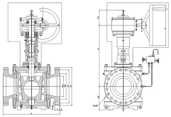
| Class | NPS | A | d | 9 | c | 0 | T | E | N-ΦD | H | H1 | H2 | G | B | Wt | Cv |
| 150 | 18 | 864 | 436 | 533.4 | 577.9 | 635 | 38.1 | 2 | 16-32 | 923 | 210 | 393 | 600 | 463 | 1385 | 10740 |
| 20 | 1016 | 487 | 584.2 | 635 | 700 | 41.3 | 2 | 20-32 | 958 | 210 | 436 | 600 | 463 | 1748 | 15460 | |
| 24 | 1219 | 589 | 692.2 | 749.3 | 815 | 46.1 | 2 | 20-35 | 1121 | 230 | 492 | 720 | 488 | 3405 | 23660 | |
| 30 | 1524 | 735 | 857.2 | 914.4 | 984 | 74.6 | 2 | 28-35 | 1269 | 250 | 590 | 860 | 770 | 7240 | 32500 | |
| 36 | 1981 | 874 | 1022 | 1085.8 | 1168 | 90.4 | 2 | 4-22 | 1500 | 250 | 730 | 860 | 815 | 11198 | 47300 | |
| 300 | 14 | 762 | 334 | 412.8 | 514.4 | 585 | 52.4 | 2 | 20-32 | 860 | 210 | 338 | 600 | 463 | 1080 | 59200 |
| 16 | 838 | 385 | 469.9 | 571.5 | 650 | 55.6 | 2 | 20-35 | 943 | 210 | 372 | 600 | 463 | 1440 | 9250 | |
| 18 | 914 | 436 | 533.4 | 628.6 | 710 | 58.8 | 2 | 24-35 | 1048 | 230 | 414 | 720 | 488 | 1895 | 11320 | |
| 20 | 990 | 487 | 584.2 | 685.8 | 775 | 62 | 2 | 24-35 | 1094 | 250 | 465 | 860 | 770 | 2220 | 16050 | |
| 24 | 1320 | 589 | 692.2 | 812.8 | 915 | 68.3 | 2 | 24-41 | 1148 | 250 | 519 | 860 | 770 | 4430 | 26590 | |
| 30 | 1651 | 735 | 857.2 | 997 | 1092 | 92 | 2 | 4-22 | 1435 | 250 | 590 | 860 | 815 | 8178 | 32990 | |
| 600 | 10 | 787 | 252 | 323.8 | 431.8 | 510 | 63.5 | 7 | 16-35 | 919 | 230 | 336 | 720 | 488 | 1055 | 5020 |
| 12 | 838 | 303 | 381 | 489 | 560 | 66.7 | 7 | 20-35 | 950 | 230 | 361 | 720 | 488 | 1375 | 9160 | |
| 14 | 889 | 334 | 412.8 | 527 | 605 | 69.9 | 7 | 20-38 | 964 | 230 | 375 | 720 | 488 | 2228 | 9400 | |
| 16 | 991 | 385 | 469.9 | 603.2 | 685 | 76.2 | 7 | 20-41 | 1132 | 250 | 413 | 860 | 770 | 2338 | 10800 | |
| 18 | 1029 | 436 | 533.4 | 654 | 745 | 82.6 | 7 | 20-44.5 | 1150 | 250 | 442 | 860 | 770 | 3566 | 13500 | |
| 20 | 1194 | 487 | 584.2 | 723.9 | 815 | 88.9 | 7 | 24-44.5 | 1336 | 250 | 479 | 860 | 815 | 4992 | 16260 | |
| 24 | 1397 | 589 | 692.2 | 838.2 | 940 | 101.6 | 7 | 24-51 | 1407 | 250 | 607 | 860 | 815 | 8154 | 2660 | |
| 900 | 2 | 368 | 50 | 92 | 165.1 | 215 | 38.1 | 7 | 8-25.5 | 514 | 185 | 186 | 460 | 330 | 97 | 155 |
| 3 | 381 | 76 | 127 | 190.5 | 240 | 38.1 | 7 | 8-25.5 | 582 | 185 | 171 | 460 | 330 | 126 | 245 | |
| 4 | 457 | 100 | 157.2 | 235 | 290 | 44.5 | 7 | 8-32 | 627 | 185 | 203 | 460 | 330 | 216 | 640 | |
| 6 | 610 | 150 | 215.9 | 317.5 | 380 | 55.6 | 7 | 12-32 | 710 | 194 | 270 | 500 | 372 | 530 | 2350 | |
| 8 | 737 | 201 | 269.9 | 393.7 | 470 | 63.5 | 7 | 12-38 | 908 | 230 | 303 | 720 | 488 | 618 | 4140 | |
| 10 | 838 | 252 | 323.8 | 469.9 | 545 | 69.9 | 7 | 16-38 | 1068 | 250 | 356 | 860 | 770 | 1956 | 5420 | |
| 1500 | 2 | 368 | 50 | 124 | 165.1 | 215 | 38.1 | 7.9 | 8-25.5 | 592 | 185 | 190 | 460 | 330 | 97 | 155 |
| 3 | 470 | 76 | 168 | 203.2 | 265 | 47.7 | 7.9 | 8-32 | 607 | 185 | 202 | 460 | 330 | 152 | 240 |
| PN | DN | A | d | g | c | o | T | E | N-ΦD | H | H1 | H2 | G | B | Wt | Cv |
| 1.6 | 450 | 864 | 436 | 550 | 585 | 640 | 40 | 4 | 20-30 | 923 | 200 | 393 | 600 | 463 | 1385 | 10740 |
| 500 | 1016 | 487 | 610 | 650 | 715 | 44 | 4 | 20-33 | 958 | 200 | 436 | 600 | 463 | 1748 | 15460 | |
| 600 | 1219 | 589 | 725 | 770 | 840 | 54 | 5 | 20-36 | 1121 | 230 | 492 | 720 | 488 | 3405 | 23660 | |
| 900 | 1981 | 874 | 1000 | 1050 | 1125 | 64 | 5 | 28-39 | 1500 | 250 | 730 | 860 | 815 | 11198 | 47300 | |
| 2.5 Female face |
350 | 762 | 334 | 450 | 490 | 555 | 38 | 4 | 16-33 | 860 | 200 | 338 | 600 | 463 | 1080 | 59200 |
| 400 | 838 | 385 | 505 | 550 | 620 | 40 | 4 | 16-36 | 943 | 200 | 372 | 600 | 463 | 1440 | 9250 | |
| 450 | 914 | 436 | 555 | 600 | 670 | 46 | 4 | 20-36 | 1048 | 230 | 414 | 720 | 488 | 1895 | 11320 | |
| 500 | 991 | 487 | 615 | 660 | 730 | 48 | 4 | 20-36 | 1094 | 250 | 465 | 860 | 770 | 2220 | 16050 | |
| 600 | 1143 | 589 | 720 | 770 | 845 | 58 | 5 | 20-39 | 1148 | 250 | 519 | 860 | 770 | 4430 | 26590 | |
| 4.0 Female face |
350 | 762 | 334 | 465 | 510 | 580 | 46 | 4 | 16-36 | 860 | 200 | 338 | 600 | 463 | 1080 | 59200 |
| 400 | 838 | 385 | 535 | 585 | 660 | 50 | 4 | 16-39 | 943 | 200 | 372 | 600 | 463 | 1440 | 9250 | |
| 450 | 914 | 436 | 560 | 610 | 685 | 57 | 4 | 20-39 | 1048 | 230 | 414 | 720 | 488 | 1895 | 11320 | |
| 500 | 991 | 487 | 615 | 670 | 755 | 57 | 4 | 20-42 | 1094 | 250 | 465 | 860 | 770 | 2220 | 16050 | |
| 600 | 1143 | 589 | 735 | 795 | 890 | 72 | 5 | 20-48 | 1148 | 250 | 519 | 860 | 770 | 4430 | 26590 | |
| 6.3 Female face |
250 | 673 | 252 | 345 | 400 | 470 | 46 | 3 | 12-36 | 919 | 230 | 336 | 720 | 488 | 1055 | 5020 |
| 300 | 762 | 303 | 410 | 460 | 530 | 52 | 4 | 16-36 | 950 | 230 | 361 | 720 | 488 | 1375 | 9160 | |
| 350 | 826 | 334 | 465 | 525 | 600 | 56 | 4 | 16-39 | 964 | 230 | 375 | 720 | 488 | 2228 | 9400 | |
| 400 | 902 | 436 | 535 | 585 | 670 | 60 | 4 | 16-42 | 1132 | 250 | 413 | 860 | 770 | 2338 | 10800 | |
| 10.0 Female face |
250 | 787 | 252 | 345 | 430 | 505 | 60 | 3 | 12-39 | 919 | 230 | 336 | 720 | 488 | 1055 | 5020 |
| 300 | 838 | 303 | 410 | 500 | 585 | 68 | 4 | 16-42 | 950 | 230 | 361 | 720 | 488 | 1375 | 9160 | |
| 350 | 889 | 334 | 465 | 560 | 655 | 74 | 4 | 16-48 | 964 | 230 | 375 | 720 | 488 | 2228 | 9400 | |
| 400 | 991 | 436 | 535 | 620 | 715 | 80 | 4 | 16-54 | 1132 | 250 | 413 | 860 | 770 | 2338 | 10800 | |
| 16.0 Female face |
50 | 368 | 50 | 102 | 145 | 195 | 30 | 3 | 4-26 | 514 | 185 | 186 | 460 | 330 | 97 | 155 |
| 80 | 381 | 76 | 138 | 180 | 230 | 36 | 3 | 8-26 | 582 | 185 | 171 | 460 | 330 | 126 | 245 | |
| 100 | 457 | 100 | 162 | 210 | 265 | 40 | 3 | 8-30 | 627 | 185 | 203 | 460 | 330 | 216 | 640 | |
| 150 | 610 | 150 | 218 | 290 | 355 | 50 | 3 | 12-33 | 710 | 194 | 270 | 500 | 372 | 530 | 2350 | |
| 200 | 737 | 201 | 285 | 360 | 430 | 60 | 3 | 12-36 | 908 | 230 | 303 | 720 | 488 | 618 | 4140 | |
| 250 | 838 | 252 | 345 | 430 | 515 | 68 | 3 | 12-42 | 1068 | 250 | 356 | 860 | 770 | 1956 | 5420 |
Dimension of Round Hole Full bore Type with Gear
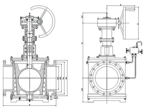
| Class | NPS | A | d | g | c | o | T | E | N- ΦD | H | H1 | H2 | G | B | Wt | Cv |
| 150 | 2 | 267 | 50 | 92 | 120.7 | 150 | 14.3 | 2 | 4-19 | 424 | 155 | 158 | 320 | 265 | 114 | 525 |
| 3 | 343 | 76 | 127 | 152.4 | 190 | 17.5 | 2 | 4-19 | 516 | 175 | 186 | 320 | 280 | 171 | 1280 | |
| 4 | 432 | 100 | 157.2 | 190.5 | 230 | 22.3 | 2 | 8-19 | 535 | 175 | 218 | 320 | 280 | 218 | 2330 | |
| 6 | 546 | 150 | 215.9 | 241.3 | 280 | 23.9 | 2 | 8-22 | 662 | 185 | 258 | 460 | 330 | 284 | 5250 | |
| 8 | 622 | 201 | 269.9 | 298.5 | 345 | 27 | 2 | 8-22 | 732 | 194 | 290 | 460 | 372 | 468 | 10800 | |
| 10 | 660 | 252 | 323.8 | 362 | 405 | 28.6 | 2 | 12-26 | 761 | 194 | 323 | 460 | 372 | 693 | 17500 | |
| 12 | 762 | 303 | 381 | 431.8 | 485 | 30.2 | 2 | 12-26 | 900 | 210 | 377 | 600 | 463 | 908 | 25600 | |
| 14 | 686 | 334 | 412.8 | 476.3 | 535 | 33.4 | 2 | 12-29 | 923 | 210 | 393 | 600 | 463 | 1308 | 31400 | |
| 16 | 762 | 385 | 469.9 | 539.8 | 595 | 35 | 2 | 16-29 | 958 | 210 | 436 | 600 | 463 | 1634 | 42500 | |
| 18 | 864 | 436 | 533.4 | 577.9 | 635 | 38.1 | 2 | 16-32 | 1042 | 230 | 484 | 720 | 488 | 3098 | 54700 | |
| 20 | 914 | 487 | 584.2 | 635 | 700 | 41.3 | 2 | 20-32 | 1067 | 230 | 507 | 7520 | 488 | 3351 | 70900 | |
| 24 | 1067 | 589 | 692.2 | 749.3 | 815 | 46.1 | 2 | 20-35 | 1269 | 250 | 590 | 860 | 770 | 6958 | 106000 |
| Class | NPS | A | d | g | c | o | T | E | N- ΦD | H | H1 | H2 | G | B | Wt | Cv |
| 300 | 2 | 283 | 50 | 92 | 127 | 165 | 20.7 | 2 | 8-19 | 500 | 175 | 159 | 320 | 280 | 142 | 520 |
| 3 | 387 | 76 | 127 | 168.3 | 210 | 27 | 2 | 8-22 | 516 | 175 | 195 | 320 | 280 | 215 | 1250 | |
| 4 | 457 | 100 | 157.2 | 200 | 255 | 30.2 | 2 | 8-22 | 539 | 175 | 218 | 320 | 280 | 238 | 2280 | |
| 6 | 559 | 150 | 215.9 | 369.9 | 320 | 35 | 2 | 12-22 | 668 | 185 | 260 | 460 | 330 | 334 | 5140 | |
| 8 | 686 | 201 | 269.9 | 330.2 | 380 | 39.7 | 2 | 12-26 | 844 | 210 | 295 | 600 | 463 | 682 | 10580 | |
| 10 | 826 | 252 | 323.8 | 387.4 | 445 | 46.1 | 2 | 16-29 | 872 | 210 | 332 | 600 | 463 | 978 | 17100 | |
| 12 | 965 | 303 | 381 | 450.8 | 520 | 49.3 | 2 | 16-32 | 964 | 230 | 378 | 720 | 488 | 1359 | 25000 | |
| 14 | 762 | 334 | 412.8 | 514.4 | 585 | 52.4 | 2 | 20-32 | 982 | 230 | 408 | 720 | 488 | 1856 | 30700 | |
| 16 | 838 | 385 | 469.9 | 571.5 | 650 | 55.6 | 2 | 20-35 | 1154 | 250 | 460 | 860 | 770 | 2174 | 41600 | |
| 18 | 914 | 436 | 533.4 | 628.6 | 710 | 58.8 | 2 | 24-35 | 1185 | 250 | 501 | 860 | 770 | 3238 | 53600 | |
| 20 | 991 | 487 | 584.2 | 685.8 | 775 | 62 | 2 | 24-35 | 1216 | 250 | 532 | 860 | 815 | 3805 | 69400 |
| Class | NPS | A | d | g | c | o | T | E | N- ΦD | H | H1 | H2 | G | B | Wt | Cv |
| 600 | 2 | 330 | 50 | 92 | 127 | 165 | 25.4 | 7 | 8-19 | 510 | 175 | 171 | 320 | 280 | 217 | 510 |
| 3 | 445 | 76 | 127 | 168.3 | 210 | 31.8 | 7 | 8-22 | 607 | 185 | 195 | 320 | 330 | 297 | 1240 | |
| 4 | 508 | 100 | 157.2 | 215.9 | 275 | 38.1 | 7 | 8-26 | 632 | 185 | 223 | 320 | 330 | 331 | 2260 | |
| 6 | 660 | 150 | 215.9 | 292.1 | 355 | 47.7 | 7 | 12-29 | 736 | 210 | 284 | 500 | 400 | 598 | 4640 | |
| 8 | 794 | 201 | 269.9 | 349.2 | 420 | 55.6 | 7 | 12-32 | 919 | 230 | 336 | 720 | 488 | 1185 | 9030 | |
| 10 | 940 | 252 | 323.8 | 431.8 | 510 | 63.5 | 7 | 16-35 | 956 | 230 | 375 | 720 | 488 | 1924 | 14790 | |
| 12 | 1067 | 303 | 381 | 489 | 560 | 66.7 | 7 | 20-35 | 1132 | 250 | 413 | 860 | 770 | 2663 | 23080 | |
| 14 | 889 | 334 | 412.8 | 527 | 605 | 69.9 | 7 | 20-39 | 1157 | 250 | 442 | 860 | 815 | 4305 | 29020 | |
| 16 | 991 | 436 | 469.9 | 603.2 | 685 | 76.2 | 7 | 20-42 | 1346 | 250 | 484 | 860 | 815 | 5164 | 39300 |
| PN | Size | A | d | g | c | o | T | E | N-ΦD | H | H1 | H2 | G | B | Wt | Cv |
| 1.6 | 50 | 267 | 50 | 100 | 125 | 160 | 16 | 3 | 4-18 | 424 | 155 | 158 | 320 | 265 | 114 | 525 |
| 80 | 343 | 76 | 135 | 160 | 195 | 20 | 3 | 8-18 | 516 | 175 | 186 | 320 | 280 | 174 | 1280 | |
| 100 | 432 | 100 | 155 | 180 | 215 | 20 | 3 | 8-18 | 535 | 175 | 218 | 320 | 280 | 218 | 2330 | |
| 150 | 533 | 150 | 210 | 240 | 280 | 24 | 3 | 8-23 | 662 | 185 | 258 | 460 | 330 | 284 | 5250 | |
| 200 | 635 | 201 | 265 | 295 | 335 | 26 | 3 | 12-23 | 732 | 194 | 290 | 460 | 372 | 468 | 10800 | |
| 250 | 787 | 323.8 | 320 | 355 | 405 | 30 | 3 | 12-25 | 761 | 194 | 323 | 460 | 372 | 693 | 17500 | |
| 300 | 864 | 381 | 375 | 410 | 460 | 30 | 3 | 12-25 | 900 | 210 | 377 | 600 | 463 | 908 | 25600 | |
| 350 | 889 | 334 | 435 | 470 | 520 | 34 | 3 | 16-25 | 923 | 210 | 393 | 600 | 463 | 1308 | 31400 | |
| 400 | 914 | 385 | 485 | 525 | 580 | 36 | 3 | 16-30 | 958 | 210 | 436 | 600 | 463 | 1634 | 42500 | |
| 450 | 1219 | 436 | 545 | 585 | 640 | 40 | 4 | 20-30 | 1042 | 230 | 484 | 720 | 488 | 3098 | 54700 | |
| 500 | 1219 | 487 | 608 | 650 | 705 | 44 | 4 | 20-34 | 1067 | 230 | 507 | 720 | 488 | 3351 | 70900 | |
| 600 | 1524 | 589 | 718 | 770 | 840 | 48 | 5 | 20-41 | 1269 | 250 | 590 | 860 | 770 | 6958 | 106000 |
| PN | Size | A | d | g | c | o | T | E | N-ΦD | H | H1 | H2 | G | B | Wt | Cv |
| 2.5 | 50 | 283 | 50 | 100 | 125 | 160 | 20 | 3 | 4-18 | 500 | 175 | 159 | 320 | 280 | 142 | 520 |
| 80 | 387 | 76 | 135 | 160 | 195 | 22 | 3 | 8-18 | 516 | 175 | 195 | 320 | 280 | 215 | 1250 | |
| 100 | 457 | 100 | 160 | 190 | 230 | 24 | 3 | 8-23 | 539 | 175 | 218 | 320 | 280 | 238 | 2280 | |
| 150 | 559 | 150 | 218 | 250 | 300 | 30 | 3 | 8-25 | 668 | 185 | 260 | 460 | 330 | 334 | 5140 | |
| 200 | 686 | 201 | 278 | 310 | 360 | 34 | 3 | 12-25 | 844 | 210 | 295 | 600 | 463 | 682 | 10580 | |
| 250 | 826 | 252 | 332 | 370 | 425 | 36 | 3 | 12-30 | 872 | 210 | 332 | 600 | 463 | 978 | 17100 | |
| 300 | 965 | 303 | 390 | 430 | 485 | 40 | 3 | 16-30 | 964 | 230 | 378 | 720 | 488 | 1359 | 25000 | |
| 350 | 965 | 334 | 448 | 490 | 550 | 44 | 4 | 16-34 | 982 | 230 | 408 | 720 | 488 | 1856 | 30700 | |
| 400 | 965 | 385 | 505 | 550 | 610 | 48 | 4 | 16-34 | 1154 | 250 | 460 | 860 | 770 | 2174 | 41600 | |
| 450 | 1219 | 436 | 555 | 600 | 660 | 50 | 4 | 20-34 | 1185 | 250 | 501 | 860 | 770 | 3238 | 53600 | |
| 500 | 1219 | 487 | 610 | 660 | 730 | 52 | 4 | 20-41 | 1216 | 250 | 532 | 860 | 815 | 3805 | 69400 |
| PN | Size | A | d | g | c | o | T | E | N-ΦD | H | H1 | H2 | G | B | Wt | Cv |
| 4.0 Female face |
50 | 283 | 50 | 100 | 125 | 165 | 20 | 3 | 4-18 | 500 | 175 | 159 | 320 | 280 | 142 | 520 |
| 80 | 387 | 76 | 135 | 160 | 195 | 22 | 3 | 8-18 | 516 | 175 | 195 | 320 | 280 | 215 | 1250 | |
| 100 | 457 | 100 | 160 | 190 | 230 | 24 | 3 | 8-23 | 539 | 185 | 218 | 320 | 280 | 238 | 2280 | |
| 150 | 559 | 150 | 218 | 250 | 300 | 30 | 3 | 8-25 | 668 | 210 | 260 | 460 | 330 | 334 | 5140 | |
| 200 | 686 | 201 | 282 | 320 | 375 | 38 | 3 | 12-30 | 844 | 210 | 295 | 600 | 463 | 682 | 10580 | |
| 250 | 826 | 252 | 345 | 385 | 445 | 42 | 3 | 12-34 | 872 | 230 | 332 | 600 | 463 | 978 | 17100 | |
| 300 | 965 | 303 | 409 | 450 | 510 | 46 | 4 | 16-34 | 964 | 230 | 378 | 720 | 488 | 1359 | 25000 | |
| 350 | 965 | 334 | 465 | 510 | 570 | 52 | 4 | 16-34 | 982 | 250 | 408 | 720 | 488 | 1856 | 30700 | |
| 400 | 965 | 385 | 535 | 585 | 655 | 58 | 4 | 16-41 | 1154 | 250 | 460 | 860 | 770 | 2174 | 41600 |
| PN | Size | A | d | g | c | o | T | E | N-ΦD | H | H1 | H2 | G | B | Wt | Cv |
| 6.3 Female face |
450 | 1219 | 436 | 560 | 610 | 680 | 60 | 4 | 20-41 | 1185 | 250 | 501 | 860 | 770 | 3238 | 53600 |
| 500 | 1219 | 487 | 612 | 670 | 755 | 62 | 4 | 20-48 | 1216 | 175 | 532 | 860 | 815 | 3805 | 69400 | |
| 50 | 330 | 50 | 105 | 135 | 175 | 26 | 3 | 4-23 | 510 | 185 | 171 | 320 | 280 | 217 | 510 | |
| 80 | 432 | 76 | 140 | 170 | 210 | 30 | 3 | 8-23 | 607 | 185 | 195 | 320 | 330 | 297 | 1240 | |
| 100 | 432 | 100 | 168 | 200 | 250 | 32 | 3 | 8-25 | 632 | 185 | 223 | 320 | 330 | 331 | 2260 | |
| 150 | 559 | 150 | 240 | 280 | 345 | 38 | 3 | 8-34 | 736 | 210 | 284 | 500 | 400 | 598 | 4640 | |
| 200 | 660 | 201 | 300 | 345 | 415 | 44 | 3 | 12-34 | 919 | 230 | 336 | 720 | 488 | 1185 | 9030 | |
| 250 | 787 | 252 | 352 | 400 | 470 | 48 | 3 | 12-41 | 956 | 230 | 375 | 720 | 488 | 1924 | 14790 | |
| 300 | 838 | 303 | 412 | 460 | 530 | 54 | 4 | 16-41 | 1132 | 250 | 413 | 860 | 770 | 2663 | 23080 |
| PN | Size | A | d | g | c | o | T | E | N-ΦD | H | H1 | H2 | G | B | Wt | Cv |
| 10 Female face |
350 | 991 | 334 | 475 | 525 | 595 | 60 | 4 | 16-41 | 1157 | 250 | 442 | 860 | 815 | 4305 | 29020 |
| 400 | 991 | 436 | 525 | 585 | 670 | 66 | 4 | 16-48 | 1346 | 250 | 484 | 860 | 815 | 5164 | 39300 | |
| 50 | 330 | 50 | 112 | 145 | 195 | 28 | 3 | 4-25 | 510 | 175 | 171 | 320 | 280 | 217 | 510 | |
| 80 | 432 | 76 | 148 | 180 | 230 | 34 | 3 | 8-25 | 607 | 185 | 195 | 320 | 330 | 297 | 1240 | |
| 100 | 432 | 100 | 172 | 210 | 265 | 38 | 3 | 8-30 | 632 | 185 | 223 | 320 | 330 | 331 | 2260 | |
| 150 | 559 | 150 | 250 | 290 | 350 | 46 | 3 | 12-34 | 736 | 210 | 284 | 500 | 400 | 598 | 4640 | |
| 200 | 660 | 201 | 312 | 360 | 430 | 54 | 3 | 12-41 | 919 | 230 | 336 | 720 | 488 | 1185 | 9030 | |
| 250 | 787 | 252 | 382 | 430 | 500 | 60 | 3 | 12-41 | 956 | 230 | 375 | 720 | 488 | 1924 | 14790 | |
| 300 | 838 | 303 | 442 | 500 | 585 | 70 | 4 | 16-48 | 1132 | 250 | 413 | 860 | 770 | 2663 | 23080 | |
| 350 | 991 | 334 | 498 | 560 | 655 | 76 | 4 | 16-54 | 1157 | 250 | 442 | 860 | 815 | 4305 | 29020 | |
| 400 | 991 | 436 | 558 | 620 | 715 | 80 | 4 | 16-54 | 1346 | 250 | 484 | 860 | 815 | 5164 | 39300 |
Reduced Bore Valve Operation Opening & Closing
Open
Closing
Full Bore Valve Operation Opening & Closing
Open
Closing
Pressure Relief System
To meet the requirement of API 6D, general dual seal plug valve used for the liquid must furnish one set of pressure relief system.
When twin seal plug valve closed properly and is full of the liquid. Due to the sunshine or hot environment, any tiny temperature fluctuation will result in the sharp variation of the pressure of the cavity.
Through the laboratory evidence, once the temperature raise 1°F. The pressure of full fuel will raise 75 Psi, certainly this data will be changed depending on the actual application conditions. (Subject to the medium, the container toughness exist air or not).
It is well known in the absolutely closed valve which is full of the liquid, may produce high pressure. So the twin seal plug valve used for liquid must equip with pressure bleed device.
Safe factor / DRT can basically realize the function of safe bleeding. However, actually all work parts are installed in the integral plate, The advantage of this device is fire safe, easy replacement for the whole part, all socket welding ends or joints, which may control to resulting in the accident effectively.
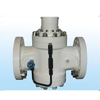
Manual bleed valve (MBV)
With the valve closed the Thermal Relief Valve releases any thermal expansion of the body liquid, back safely and automatically, to the line. Relief set at 25 Psi.*
Note: the "goose neck" pipe to prevent drainage of the body liquid.
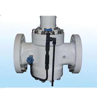
Thermal relief to body (TRB)
With the valve closed the Thermal Relief Valve releasesany thermal expansion of the body liquid, back safely and automatically, to the line. Relief set at 25 Psi.*
Thermal relief to atmosphere (TRA)
Similar to TRB except thermal relief valve is set at 50 Psi above pipeline rated pressure and is vented to atmosphere.
Manual bleed valve with thermal relief (MTR)
The manual bleed proves drop tight sealing. The Thermal Relief Valve releases any thermal expansion of the body liquid, back safely and automatically to the line. Relief set at 25 Psi.
Manual bleed valve with gauge (MBG)
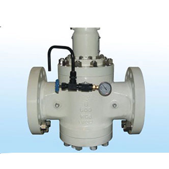
The manual bleed valve is combined with a gauge when emission to atmosphere is undesirable. The closing action of a valve automatically reduces body cavity pressure due to the expanding seating segments.
The gauge alone will indicate tight seals. (After a period of time, body pressure may again increase due to thermal expansion of fluid in the body cavity).
Thermal relief valve with gauge (TRG)
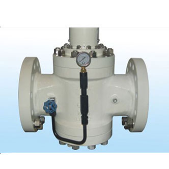
A thermal relief valve, to relieve anybody pressure which may build up due to thermal change, is combined with a gauge to indicate tight seals. No emissions to atmosphere. No sump system required. Relief set at 25 Psi.
The gauge alone will indicate tight seals. (After a period of time, body pressure may again increase due to thermal expansion of fluid in the body cavity).
*When a manual bleed or automatic bleed is fitted, the vent pipe should always be above the highest point of the valve body cavity. This will prevent liquid in the body cavity from dripping out.
Leakage past either seal would expel liquid from the already-full body cavity.
*The relief valve is set to open at 25 Psi on all valves, regardless of their working pressure.
With the valve closed, the relief valve will open at 25 Psi above upstream pressure.
This system functions only when the valve is closed and the isolation valve Is open.
CAUTION
A thermal relief system, piped back to the valve throat, converts the valve to a “DIRECTIONAL" valve. Thermal relief should always be piped back to the upstream side.
If It were piped to the downstream, any leakage past the main seal on the "up" side would be permitted to by-pass the "down" seal, by way of the directional check valve.
Thermal relief systems are designed to relieve excess pressure rise in the body cavity of a closed valve due to ambient temperature causing expansion of the liquid in the valve.
Some fluid is emitted at each actuation. A sump system is important as fluid will spurt out as the valve approaches the closed position and the cam opens the ABV. The spurting will cease as valve is fully closed for positive verification of double sealing.
Note: All automated valves require some form of body pressure relief. TRB/TRA/MTR/ABV/TRG
In normal service, the manual bleed is kept closed, unless to check for tightness or to vent thermal pressure rise. With automatic bleed or thermal relief back-to-line, the manual isolation valve that is attached to the body must always be open, except for maintenance. If the isolation valve is closed, the relief system cannot operate.