ZZYP Self Acting Pressure Reducing Valve (PRV)
Self Acting Pressure Reducing Valves
Introductions
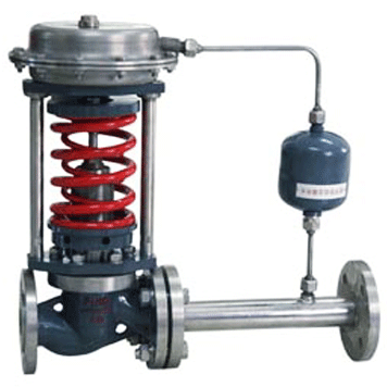
ZZYP type self acting pressure reducing valve is a valve that without any external energy, using controlled media energy as power source, introduce the implement diaphragm to produce thrust, control the throttle components movement to achieve the automatic regulation. It has the comprehensive functions of measurement, implementation, control.
It can be used in no gas, no electricity places, and widely used for automatic control in petroleum, chemical, power station, light industry, printing and dyeing industry self-control system of various equipment gases, liquids and steam medium pressure deceleration and regulation (regulating pressure after the valve), pressure relief and regulation (regulating pressure before the valve). According to the users different working conditions, we can choose different valve core structure type and different actuator, in order to achieve the best control effect.
Dimensions & Constructral Diagram
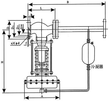
Self Acting Pressure Reducing Valve Constructral Diagram
| category | model | category | model |
| single seat press closed type | ZZYP-16~64B | single seat press closed type | ZZYP-16~64K |
| double seat press closed type | ZZYN-16~64B | double seat press closed type | ZZYN-16~64K |
| sleeve press closed type | ZZYM-16~64B | sleeve press closed type | ZZYM-16~64K |
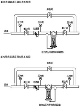
Notes: 1. Press closed type regulates pressure after the valve, when the pressure increases after valve, the valve is closed, to achieve decompression, regulation purposes.
2. Press open type regulates pressure after the valve, when the pressure increases after valve, the valve opens, to achieve pressure relief, and regulation purpose.
Main Performance
| control accuracy% | ±8 | |||||||||||
| allowed leakage | hard sealing(L/H) | single seat(Ⅳ level):≤ 10-4 valve rated capacity: double seats、sleeve(Ⅱ level)、≤ 5×10⁻³×valve rated capacity | ||||||||||
| soft sealing(ml/min) | DN(mm) | |||||||||||
| 20 | 25 | 32 | 40 | 50 | 65 | 80 | 100 | 125 | 150 | 200 | ||
| 0.15 | 0.3 | 0.45 | 0.6 | 0.9 | 1.7 | 4.0 | 6.75 | |||||
Main Technical Parameters
| Nominal Diameter DN(mm) | 20 | 25 | 32 | 40 | 50 | 65 | 80 | 100 | 125 | 150 | 200 | |||
| seat diameter DN(mm) | 10 | 12 | 15 | 20 | ||||||||||
| rated Flow Coefficient Kv | 1.8 | 2.4 | 4.4 | 4 | 11 | 20 | 30 | 48 | 75 | 120 | 190 | 300 | 480 | 760 |
| allowed pressure differentia(MPa) | 2.5 | 2.0 | 1.6 | 1.0 | ||||||||||
| nominal pressure(MPa) | 1.6 4.0 6.4 | |||||||||||||
| intrinsic flow characteristic | fast open | |||||||||||||
| minimum pressure differentia of ensuring regulating valve operation P(MPa) | 0.05 | |||||||||||||
| pressure subsection scope (KPa) | 15~50 40~80 60~100 80~140 120~80 160~220 200~260 240~300 280~350 330~400 380~450 430~500 480~560 540~620 600~700 680~800 780~900 800~1000 900~2000 | |||||||||||||
| working temperature °C | liquid≤ 140;gas≤ 80; equipped with condensers and heat sinks ≤ 350 | |||||||||||||
| applicable medium | gas, steam, low viscosity liquids | |||||||||||||
| flange dimension, type | PN10、16、40GB9113-88、PN64JB/T7-94;PN10,16 BULGE,PN40,64 female type match other standard type flange according to customers requirements(如such as:ANSI、JIS、DIN,etc) | |||||||||||||
| face to face dimension | According to GB12221-89 standard | |||||||||||||
| matched components | Condensers (for medium steam occasions), heat sinks, etc. | |||||||||||||
| actuator signal connector | internal thread M16×1.5 | |||||||||||||
Note: Pressure sub-section scope can be designed according to user requirements.
Installation Examples
External Dimensions and Weight
| Nominal Diameter(DN) | 20 | 25 | 32 | 40 | 50 | 65 | 80 | 100 | 125 | 150 | 200 | ||
| L | PN16、40 | 150 | 160 | 180 | 200 | 230 | 290 | 310 | 350 | 400 | 480 | 600 | |
| PN64 | 230 | 230 | 260 | 260 | 300 | 340 | 380 | 430 | 500 | 550 | 650 | ||
| B | 233 | 332 | 373 | 522 | 673 | 980 | 1200 | ||||||
| H | pressure regulation scope MPa | 15~140 | 475 | 520 | 540 | 710 | 780 | 840 | 880 | 915 | |||
| 120~300 | 455 | 500 | 520 | 690 | 760 | 800 | 870 | 880 | |||||
| 280~500 | 450 | 490 | 510 | 680 | 750 | 790 | 860 | 870 | |||||
| 480~1000 | 445 | 480 | 670 | 740 | 780 | 850 | 860 | ||||||
| 600~1500 | 445 | 570 | 600 | 820 | 890 | 950 | 950 | 1000 | |||||
| 1000~2500 | 445 | 570 | 600 | 820 | 890 | 950 | 950 | 1000 | |||||
| A | pressure regulation scope MPa | 15~140 | Φ282 | Φ308 | |||||||||
| 120~300 | Φ232 | ||||||||||||
| 280~1000 | Φ196 | Φ196 | Φ282 | ||||||||||
| 600~2500 | Φ85 | Φ96 | |||||||||||
| approximately weight(Kg) | 26 | 37 | 42 | 72 | 90 | 114 | 130 | 144 | 180 | ||||
| impluse pipe interface thread | M16×15 | ||||||||||||
All Categories
- Ball Valves
- Control Valves
- Check Valves
- Globe Valves
- Butterfly Valves
- Bellows Sealed Valves
- Pressure Reducing Valves
- Plug Valves
- Safety Valves
- Safety Relief Valves
- Resilient Seated Gate Valves
- Cast Steel Valves
- Forged Steel Valves
- Instrumentation Ball Valves
- Instrument Manifolds
- Needle & Gauge Valves
- Balance Valves