500X Pressure Relief, Pressure Sustaining Valve
Overview
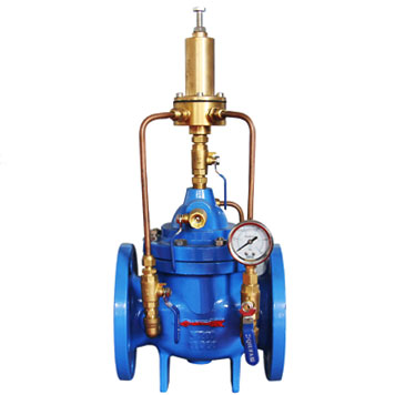
500X Pressure Relief, Pressure Sustaining Valve maintains the inlet pressure at minimal reselected value. To hold a steady line pressure the valve is opening fast and closed gradually to prevent surge. If installed on a by-pass line, main line pressure is accurately controlled by relief of excess pressure.
500X Control Valve is used in the pipeline system to prevent of surpassing pressure or to keep the pressure of it, to reduce the water hammers shock after the pump is closed and also used as a water hammer remover in the large water supply system.
A self cleaning filter screen is placed on the inlet of the valves control system, which stops the suspension grains of the bigger specific gravity and diameter from going into the system by means of the bigger specific gravity of the fluid to ensure the main valves water supply pressure at the upstream at the set value, and to get the system circulated smoothly without any resistance. This valve features by sensitive open-close, safety, reliability, stable motion and long duration.
Materials
| Serial No. | Part | Material |
| 1 | Body | Cast Iron (GG25, HT200) / Ductile Iron (GG40, QT) |
| 2 | Pin | Bronze |
| 3 | Seat | 410 S.S. / SS 304 / SS 316 |
| 4 | O-ring Gasket | NBR |
| 5 | O-ring | NBR |
| 6 | O-ring washer | Cast Iron |
| 7 | O-RING | NBR |
| 8 | Stem | 410 S.S. / SS 304 / SS 316 |
| 9 | Disc | Cast Iron (GG25, HT200) / Ductile Iron (GG40, QT) |
| 10 | Diaphragm | Rubber |
| 11 | Diaphragm washer | Bronze |
| 12 | Ball valve | Bronze |
| 13 | Nut | H62 |
| 14 | Spring | ASTM 6150 |
| 15 | Cover | Cast Iron (GG25, HT200) / Ductile Iron (GG40, QT) |
| 16 | Pilot Socket | H62 |
| 17 | Nut | 35 |
| 18 | Stud | 35 |
| 19 | Ball valve | Bronze |
| 20 | Pressure relief valve | Bronze |
| 21 | Ball Valve | Bronze |
| 22 | Pressure show | |
| 23 | Needle valve | Bronze |
| 24 | Micro-strainer | 304 |
| 25 | Connection socket | Cast Iron |
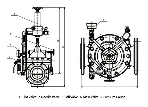
Dimensions
| DNmm | 20 | 25 | 32 | 40 | 50 | 65 | 80 | 100 | 125 | 150 | 200 | 250 | 300 | 350 | 400 | 450 | 500 | |
| L | 180 | 180 | 180 | 203 | 203 | 235 | 285 | 360 | 400 | 455 | 585 | 650 | 800 | 860 | 915 | 980 | 1075 | |
| PN10 | D | 105 | 115 | 135 | 145 | 160 | 180 | 195 | 215 | 245 | 280 | 335 | 390 | 440 | 500 | 565 | 615 | 670 |
| D1 | 75 | 85 | 100 | 110 | 125 | 145 | 160 | 180 | 210 | 240 | 295 | 350 | 400 | 460 | 515 | 565 | 620 | |
| PN16 | D | 105 | 115 | 135 | 145 | 160 | 180 | 195 | 215 | 245 | 280 | 335 | 405 | 460 | 520 | 580 | 640 | 705 |
| D1 | 75 | 85 | 100 | 110 | 125 | 145 | 160 | 180 | 210 | 240 | 295 | 355 | 410 | 470 | 525 | 585 | 650 | |
| PN25 | D | 105 | 110 | 135 | 145 | 160 | 180 | 195 | 230 | 270 | 300 | 360 | 425 | 485 | 550 | 610 | 660 | 730 |
| D1 | 75 | 85 | 100 | 110 | 125 | 145 | 160 | 190 | 220 | 250 | 310 | 370 | 430 | 490 | 550 | 600 | 660 | |
| H | 550 | 550 | 550 | 610 | 610 | 625 | 645 | 750 | 808 | 864 | 1135 | 1185 | 1325 | 1385 | 1445 | 1325 | 1430 | |
| H1 | 460 | 460 | 460 | 516 | 516 | 520 | 538 | 596 | 655 | 710 | 805 | 855 | 955 | 990 | 1030 | 905 | 960 | |
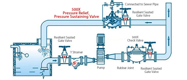
Installation
All Categories
- Ball Valves
- Control Valves
- Check Valves
- Globe Valves
- Butterfly Valves
- Resilient Seated Gate Valves
- Pressure Reducing Valves
- Plug Valves
- Safety Valves
- Safety Relief Valves
- Bellows Sealed Valves
- Cast Steel Valves
- Forged Steel Valves
- Instrumentation Ball Valves
- Instrument Manifolds
- Needle & Gauge Valves
- Balance Valves